

 Thanks:
  Likes:


@Electrojake brings up a good point, you will need to have a multimeter and a basic knowledge of DC circuits to troubleshoot this issue. Looking at the electrical diagram provided in the previous attachment I would suggest starting off by testing and eliminating half of the circuit.
To do this label and remove the two small wires from the heater relay (wires K174 from terminal 85 & K974 from terminal 86 on diagram).
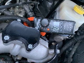
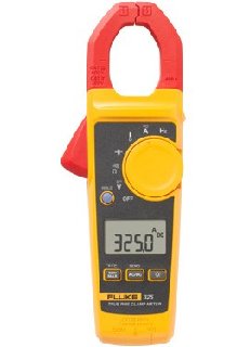
Insulate each wire with electrical tape. I would then attach a DC clamp on ammeter capable of measuring up to 300 amps around the wire going to the intake heater(wire A19 or A122 on diagram) Next apply battery power (+/-12VDC) to the solenoid terminals CAUTION: do not apply any voltage to the K174 or K974 wires or you will fry your PCM apply voltage to the solenoid terminals momentarily while watching the ammeter.
If the ammeter measures approximately 220 amps DC the test is compete and you know for sure the heater circuit, fusible link, heater element, and solenoid are all good. CAUTION: do not leave the solenoid energized for any longer than 30 seconds as you could burn out the heater element.
If the test was successful then this leaves the two small heater relay wires to troubleshoot by checking continuity between each wire from wire harness C2 on the PCM pins 75 to terminal 85 & pin 76 to terminal 86.
Again this is the way I would troubleshoot this issue, do not attempt if you are not comfortable or don’t understand my suggestions.
2014 RAM 3500 (Aisin) 3.73 4X4 Limited Crew Cab Long Bed DRW. Oil Bypass Filter, 50 Gallon auxiliary fuel tank.
Sent from my iPad using Tapatalk


Bookmarks